Intermatic Timer Switch Wiring Diagram
Use solid or stranded copper only wire with insulation to. Intermatic incorporated ts spring grove, illinois time pointer time dial off tripper manual lever on tripper.
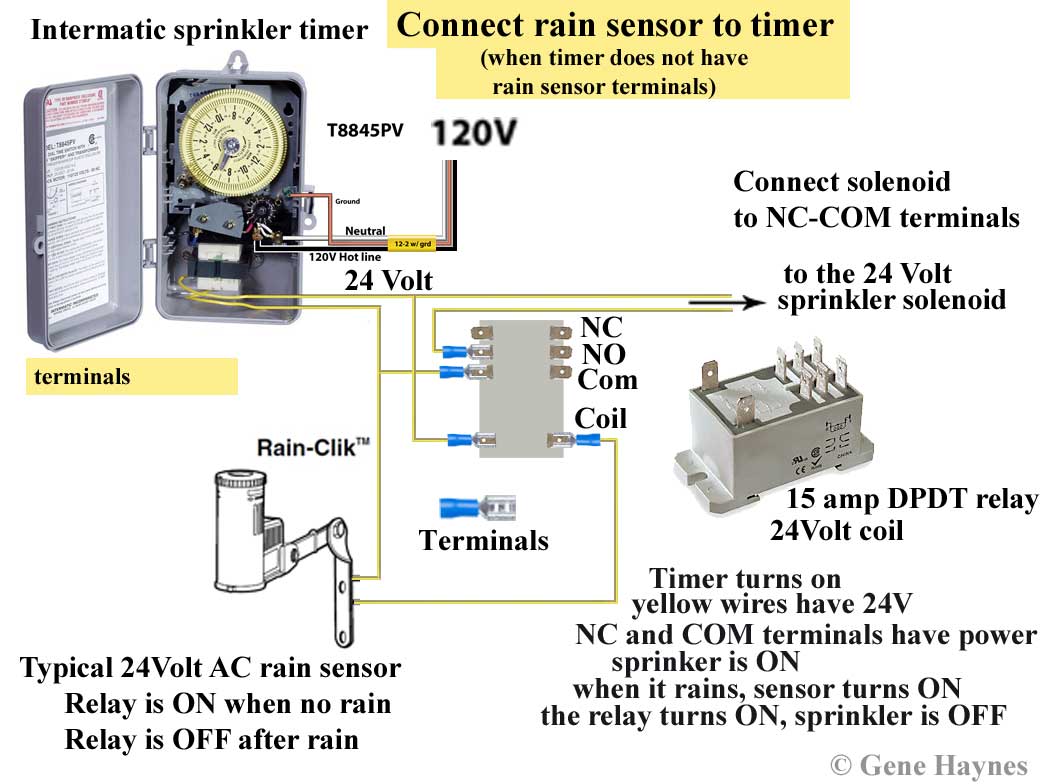
Intermatic Sprinkler Timer Wiring Diagram
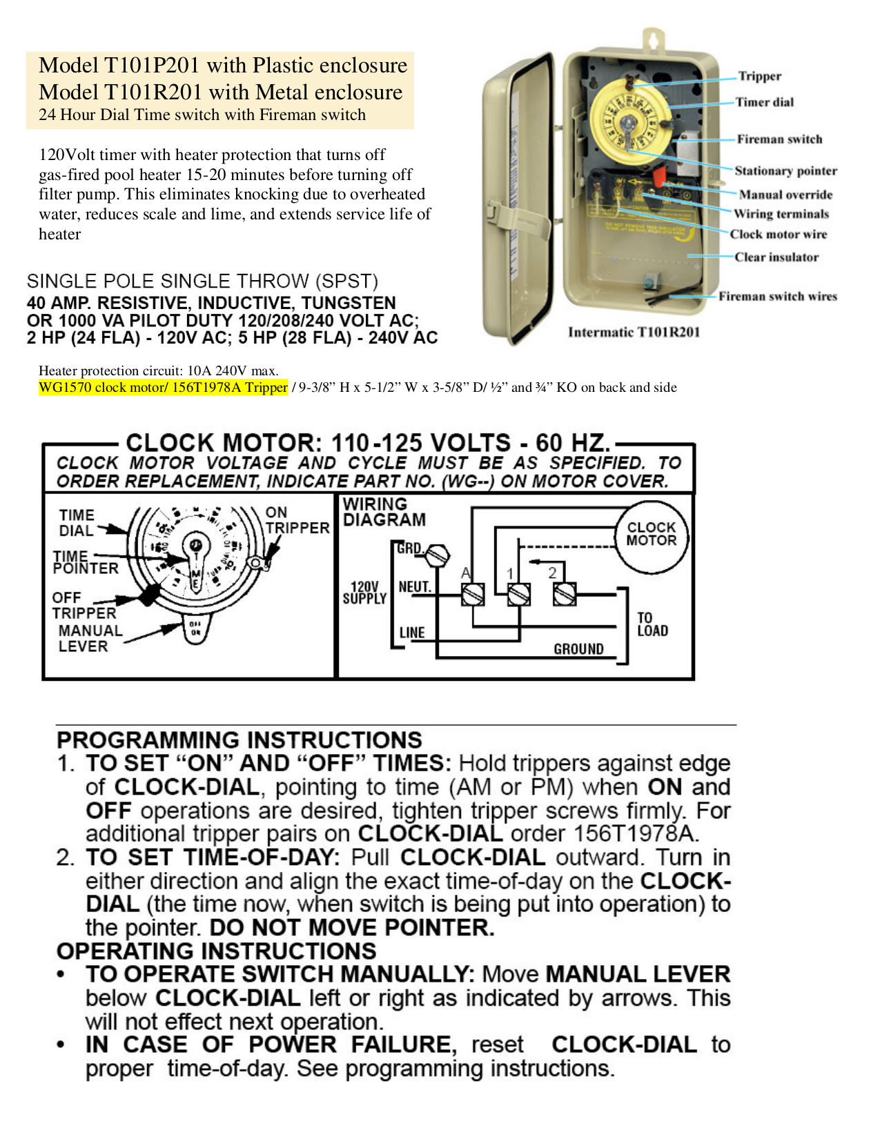
To order replacement, indicate part no.

Intermatic timer switch wiring diagram. A wiring diagram is a type of schematic which utilizes abstract pictorial signs to reveal all the interconnections. Be sure thatall the wire nuts are secure. (see “other installations” if switching from 3 or more.
It shows the components of the circuit as simplified shapes, and the knack and signal links together with the devices. 24 hour dial time switch double pole single throw (dpst) 40 amp. On intermatic 240v timer wiring diagram.
Intermatic pool timer wiring diagram. To wire switch follow diagram above. These dependable time switches can handle electrical loads up to 40 a per.
Connect the ground wire to the green. Sometimes the wires will cross. To clear the timer press and hold down the on off button.
These dependable time switches can handle electrical loads up to 40 a per pole and allow for up to 12 on/off operations per day. User guide (20 pages) switch intermatic et series owner/installer instruction manual. According to earlier, the traces in a intermatic pool timer wiring diagram represents wires.
Wire size min #14 awg: Ah3 delay timer and relay timer relay basic electrical wiring. But, it doesn’t mean link between the wires.
Ground to ground, and the switched black line on terminal 2, and unswitched on. Cap the red wire with a wire nut. The 555 timer starts timing when switched on.
Intermatic time clock wiring diagram. Sometimes, the wires will cross. Intermatic incorporated manufactures timer switches designed for indoor and outdoor use.
Each wire set contains two insulated and one bare wire. How to install an intermatic t timer most popular. Intermatic pool pump timer t101r bypass in 240v system wh40 water heater time wiring t104 off how to connect t101 indoor 24 hour t104r won t turn on replace mechanical instructions et1105 t103 operating clock parts wire a switch r8800 series 3 hp 220 volt r8806p101c outlet wall lighting timers replacement.
For other installations, visit www.intermatic.com or consult a qualified electrician. Wire size max #8 awg: Strip 1 2 inch of the covering from each insulated wire entering the intermatic timer with wire strippers.
Intermatic timers wiring instructions pdf manualzz. To wire switch follow diagram above. Variety of intermatic st01 wiring diagram.
Time pointer time dial off tripper manual lever on tripper typical wiring diagram clock motor 120/240 volt 3 wire supply to loads ground line 2 line 1 a 2 4 gr. Injunction of two wires is generally indicated by black dot to the intersection of 2 lines. There will be primary lines that are represented by l1, l2, l3, and so on.
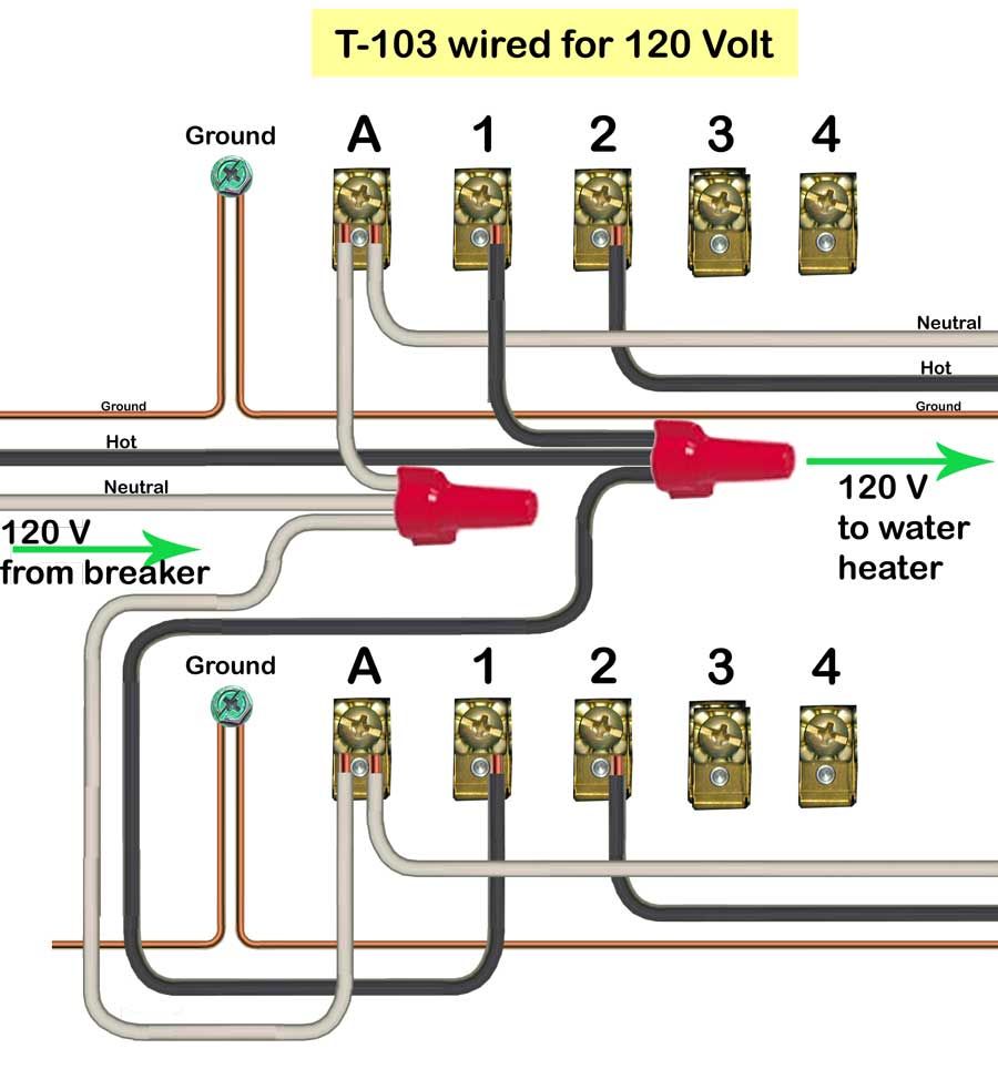
Outgoing, the 2 white wires are wirenutted with the white incoming line and again all tied to terminal a. An intermatic timer switch saves electricity when it turns a water heater off at night and when it limits the amount of time a pool s filtration system runs. Intermatic timer t104 wiring diagram wiring diagram is a simplified tolerable pictorial representation of an electrical circuit.
In the intermatic t103 box is a wiring diagram as attached. Use solid or stranded copper only wire with insulation to suit installation. 24 hour dial time switch double pole single throw (dpst) 40 amp.
Wire c jumper diagram 2. Wiring instructions:to wire switch follow diagram above. The black wire from the timer, using the wire nuts provided.
Connect the other building wire to the blue wire from the timer. These dependable time switches can handle electrical loads up to 40 a per.jul 18, · t timer wiring diagram intermatic wall timer instructions intermatic wall timer instructions buy now model overview specifications resources digital timer with astro random and dst. Find your intermatic pool timer wiring diagram here for intermatic pool timer wiring diagram and you can print out.
Use solid or stranded copper only wire with insulation to. Intermatic pool timer wiring diagram just whats wiring diagram. Black to terminal 1, red to terminal 3, white to terminal a, ground to ground terminal.
Wiring instructions:to wire switch follow diagram above. To wire switch follow diagram above. In the wiring diagram is says neutral.
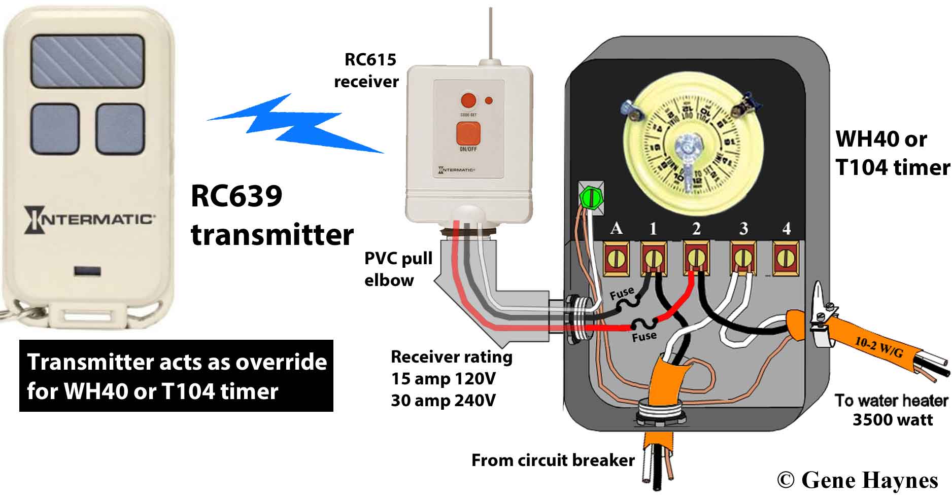
Wire “c” jumper diagram 3: Many pool pump motors and water heaters use intermatic timers to regulate their run times. An intermatic timer switch saves electricity when it turns a water heater off at night and when it limits the amount of time.
Clock motor voltage and cycle must be as specified. Intermatic t basic wiring diagram, t timer volts or volts check label on side of water heater for volts & watts this timer. When i connect it to the white neutral bar in the fuse box it trips the gfi same if i connect it to the ground bar this is a double pole switch with gfi.
A wiring diagram is a simplified standard photographic depiction of an electric circuit. February 9, 2022 on timer switch wiring diagram. The t series mechanical time switch has proven it can stand the test of time.
Intermatic makes a freeze protection control that wires directly into a v timer. Use solid or stranded copper only wire with insulation to suit. Intermatic t 104 wiring diagram.
The t series mechanical time switch has proven it can stand the test of time. Wiring diagram 240 v 2 wire and ground clock motor: An example of single pole and three way wiring follow.
Reliable and low maintenance, these solutions are an ideal choice to pair with water pumps, lights, fans, water heaters and other electrical loads. Most pool pump timers are time operated double throw switches meaning a timer controls a switch that connects to both wires entering and leaving the.
Intermatic T101 Timer Wiring Diagram
Intermatic T101 Timer Wiring Diagram General Wiring Diagram
Intermatic St01 Wiring Diagram Free Wiring Diagram
Intermatic Pool Pump Timer Wiring Diagram
Intermatic P1353me Wiring Diagram

Intermatic Timer Wiring Diagram T101 General Wiring Diagram
Intermatic T104r Wiring Diagram
Intermatic T104 Wiring Diagram
Intermatic Timer T104 Wiring Diagram Download

[DIAGRAM] Intermatic E10694 Pool Timer Wiring Diagram FULL Version HD Quality Wiring Diagram
How To Wire A Light Switch Timer Perfect Fresh Intermatic Pool Timer Wiring Diagram Irelandnews

Intermatic Timer T104 Wiring Diagram Download

Intermatic R8806p101c Wiring Diagram Collection

Intermatic Timer Wiring Diagram General Wiring Diagram

30 Intermatic T101 Timer Wiring Diagram Wiring Diagram Database

Tork Wiring Schematic for Lighting Contactor and Photocell Wiring Diagram Image

Intermatic Timer T104 Wiring Diagram Download

How to wire Intermatic sprinkler and irrigation timers and manuals

Intermatic Timer Wiring Diagram T101